
DIY Mass Flow Controller Interface
When the Fusor is in operation, it’s useful to know how much deuterium is entering the chamber for data collection purposes. Having some control over this flow is vital for exact operation of the Fusor. This is where a mass flow controller comes in to play, which both measures and controls the flow of gas.
Because the mass of a given gas volume changes with pressure, measuring the volumetric flow rate in the deuterium line of the fusor would not be accurate, as the pressure in the deuterium line is not constant. A mass flow controller gives an exact measure of the amount of gas flowing in terms of standard cubic centimetres per minute (SCCM), which accounts for differences in temperature and pressure affecting how much gas is flowing. You can read more about how they work here, or check out Ben Krasnow’s video.
I picked up a Mass flow controller on eBay, a Hastings-Teledyne HFM-300. The specific unit was configured for a maximum 10SCCM flow of N2. Mass flow controllers are built to cater to a specific gas, but conversion tables exist for taking a reading for a non-configured gas and converting it to a real flow rate. I got an N2 device on purpose, because the conversion factor between deuterium and N2 is 1.00, or 0.99, which requires no actual converting.
If I was buying things brand new, I’d be able to get a plug and play controller for the MFC and be up and running immediately. However, buying second-hand and surplus is a different story, and I just got the MFC itself, nothing more, nothing less, and needed to set up a control and read-out for it myself. The MFC has a D-sub 15 pin connector on it for control, and thankfully the datasheet is still available. With that in hand and after asking some guys for a bit of advice (this is new territory for me), it was fairly straightforward to get set up.
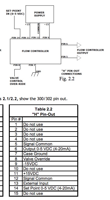
A D-sub soldering socket/connector from Farnell linked the pin connections and everything was routed through a breadboard I have from an Arduino Uno starter kit. The MFC takes a ±15V power input, which I got from an XP POWER ECL15UD02-S block. Other than the power input, the MFC takes a 0-5v analog input proportional to flow rate desired, and outputs a 0-5v signal proportional to actual flow rate. There’s also ground connections and so on. An Arduino Uno was used for these. As the MFC takes an analog input, I was iffy about whether or not the Arduino’s PWM would work by itself (not an analog signal). Sam Zeloof helped here - told me to use an RC low-pass filter on the PWM and that’d give the desired 0-5v analog output, which worked a charm. Input is set with a potentiometer input to the Arduino, which gives me more hands-on control than computer-input values.
The setup was tested with Dad’s compressor, and the MFC was reading flow rates just fine, but not responding to them. I.e there was no control of flow, just reading and response. I couldn’t figure out what was wrong after checking everything with a multimeter and oscilloscope and posted on fusor.net. Quickly figured out the HFM-300 is only a mass flow meter, and not a controller. Whoops. Everything was set up fine, just the device doesn’t actually have any capability to control flow and is not an actual MFC. It was listed as an MFC, but I guess I didn’t do my research to confirm it.
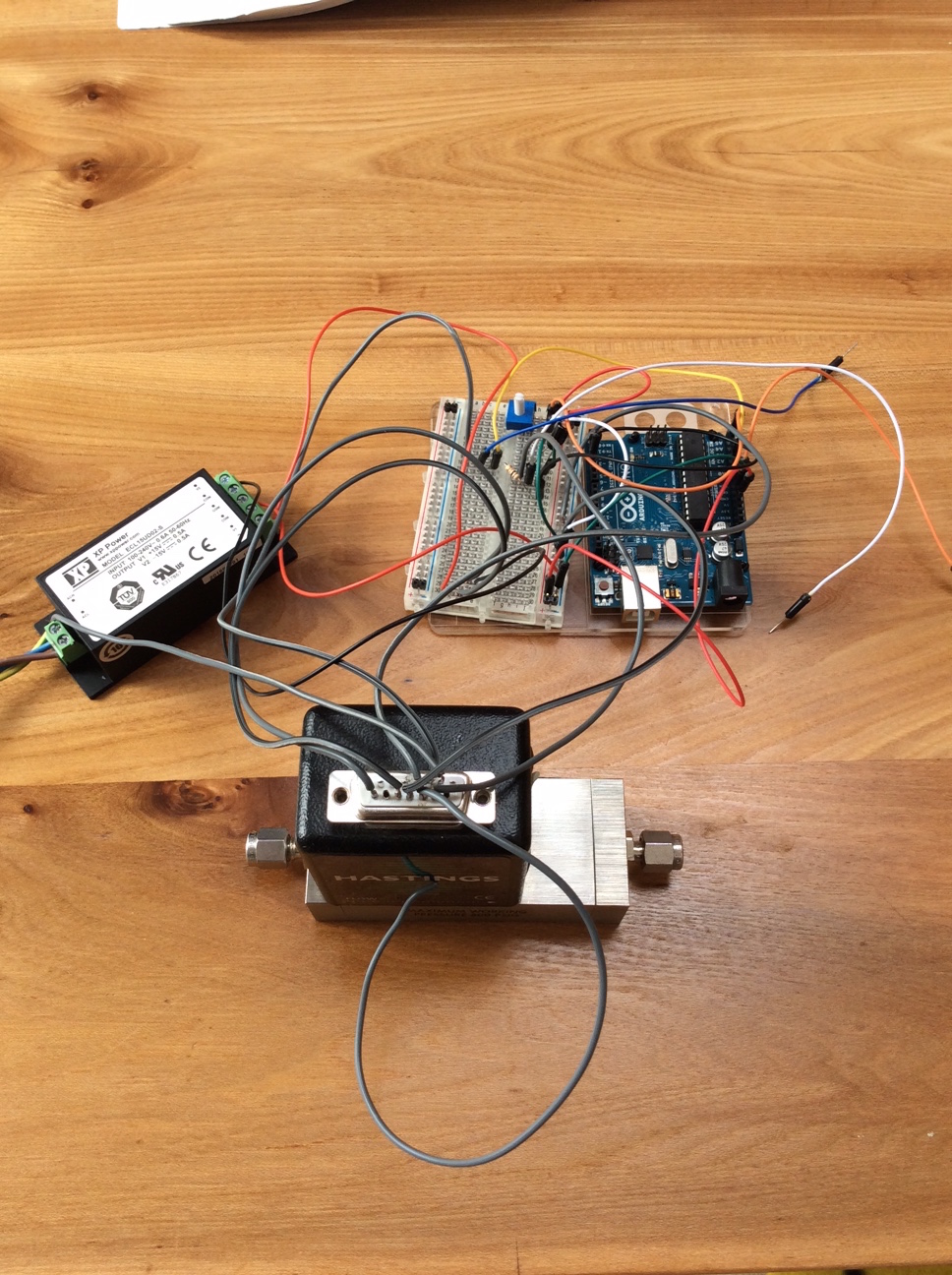
Next steps are to buy an actual MFC, and package everything up a bit nicer for ease of use, it looks a bit hectic at the moment. The Arduino Uno will be replaced with a cheap Nano. Most MFCs have almost identical control schemes, so the bulk of the work is done and there’ll just be minor adjustments to cater to the specifics of whatever replacement model I get.
Thanks to Sam Zeloof and Andy Busse for their help.